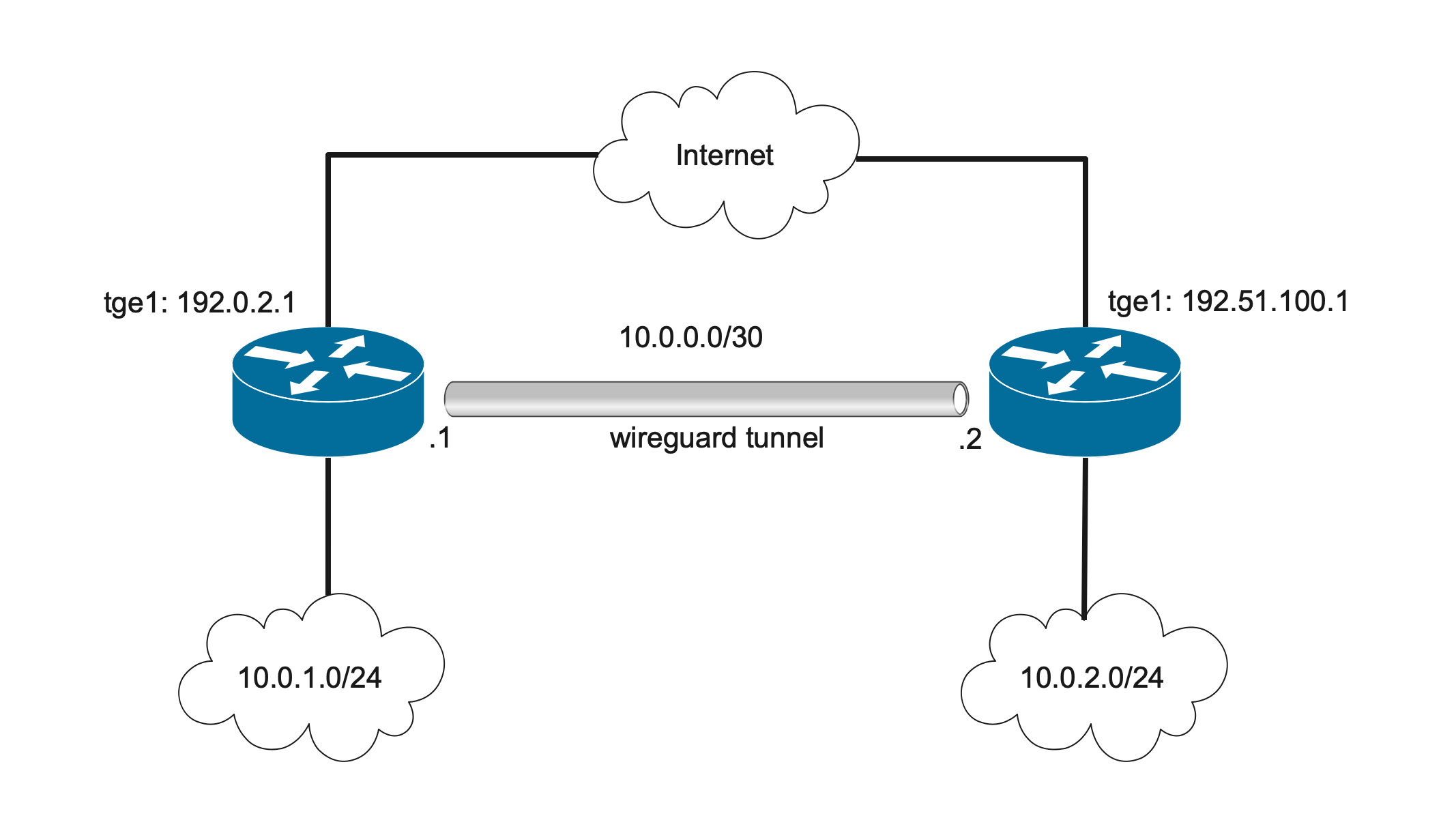
WireGuard site-to-site example
This example shows a simple configuration that connects NetX routers via WireGuard tunnel.
Topology

Address plan
NetX routers use the following interfaces and addresses:
- rt-netx-a: interface
tge1, WAN interface, 192.0.2.1/24 - rt-netx-a: interface
wg0, WireGuard interface, 10.0.0.1/30 - rt-netx-b: interface
tge1, WAN interface, 192.51.100.1/24 - rt-netx-b: interface
wg0, WireGuard interface, 10.0.0.2/30
As the first step, WAN interfaces are configured on both rt-netx-a and rt-netx-b.
! set up tge1 addresses on rt-netx-a
rt-netx-a# interface tge1 ipv4 address 192.0.2.1/24

! set up tge1 addresses on rt-netx-b
rt-netx-b# interface tge1 ipv4 address 192.51.100.1/24
WireGuard config
- Creating WireGuard interface can be done using
interface wg0command. This command creates WireGuard interface and generates private/public key-pair. The following config creates WireGuard interfaces on both routesrt-netx-aandrt-netx-b, diplays their public-keys and sets-up IPv4 address.
rt-netx-a# interface wg0
rt-netx-a(if-wg0)# ipv4 address 10.0.0.1/30
rt-netx-a(if-wg0)# show public-key
ChfUFxmTe76HqX4pAaDSaXqh/Bgi7w5qc5GGqVRKnlI=
rt-netx-b# interface wg0
rt-netx-b(if-wg0)# ipv4 address 10.0.0.2/30
rt-netx-b(if-wg0)# show public-key
ukhouOiMAMwpVqCFITVjifatTlwhYgmQm3am0zvL11E=
- As the next step, it's neccessary to configure a peer on both routers.
! The following command switch to interactive mode, where a peer can be defined
rt-netx-a(if-wg0)# peer
- The
[Interface]section is created automatically. The peer section configure rt-netx-b as a WireGuard peer. Syntax for the configuration file is the same as WireGuard config file.
[Interface]
ListenPort = 51820
PrivateKey = MOqXAXUo1veELBOYSNtUSv4p6UGhMDde97....

[Peer]
PublicKey = ukhouOiMAMwpVqCFITVjifatTlwhYgmQm3am0zvL11E=
Endpoint = 192.51.100.1:51820
AllowedIPs = 10.0.2.0/24
- The same step is done on rt-netx-b with rt-netx-a's public key.
rt-netx-b(if-wg0)# peer

[Interface]
ListenPort = 51820
PrivateKey = cMhAKREuLz9RkDr6nJPlNcWfiVuV.....

[Peer]
PublicKey = ChfUFxmTe76HqX4pAaDSaXqh/Bgi7w5qc5GGqVRKnlI=
Endpoint = 192.0.2.1:51820
AllowedIPs = 10.0.1.0/24
- Enable wg0 interfaces both on rt-netx-a, and rt-netx-b.
rt-netx-a(if-wg0) no shutdown

! The same is done on rt-netx-b
rt-netx-b(if-wg0) no shutdown
- It's necessary to also set-up proper routing between subnets (if dynamic routing protocol is not in used)
! Let's create a static route on rt-netx-a pointing to rt-netx-b's subnet
rt-netx-a# ipv4 route 10.0.2.0/24 10.0.0.2

! The same is done on rt-netx-b, static route points to rt-netx-a's subnet
rt-netx-b# ipv4 route 10.0.1.0/24 10.0.0.1
Note
Standard Linux WireGuard installation configure appropriate routes using wg-quick tool. NetX uses a different
approach as it's up to an administrator to configre routing according his/her needs.
show peercommand can be used to display the status of the WireGuard tunnel. The following output shows the status of the WireGuard tunnel on rt-netx-a.
rt-netx-a(if-wg0)# show peer
peer: ukhouOiMAMwpVqCFITVjifatTlwhYgmQm3am0zvL11E=
  endpoint: 192.51.100.1:51820
  allowed ips: 10.0.2.0/24
  latest handshake: 1 hour, 46 minutes, 13 seconds ago
  transfer: 1.62 KiB received, 2.54 KiB sent
- The ping command can be used to verify the end-to-end reachability.
rt-netx-a(if-wg0) ping source 10.0.1.1 10.0.2.1
ping -c 3 -I 10.0.1.1 10.0.2.1
PING 10.0.2.1 (10.0.2.1) from 10.0.1.1 : 56(84) bytes of data.
64 bytes from 10.0.2.1: icmp_seq=1 ttl=64 time=0.515 ms
64 bytes from 10.0.2.1: icmp_seq=2 ttl=64 time=0.974 ms
64 bytes from 10.0.2.1: icmp_seq=3 ttl=64 time=1.09 ms

--- 10.0.2.1 ping statistics ---
3 packets transmitted, 3 received, 0% packet loss, time 2033ms
rtt min/avg/max/mdev = 0.515/0.859/1.090/0.250 ms
Note
The ping command uses source option to select source IPv4 address. Without the source option,
NetX selects the best address for outgoing ICMP request, which is IPv4 address of the WireGuard interface (10.0.0.1).
This address, is however, not included in AllowedIPs, thus traffic is dropped.